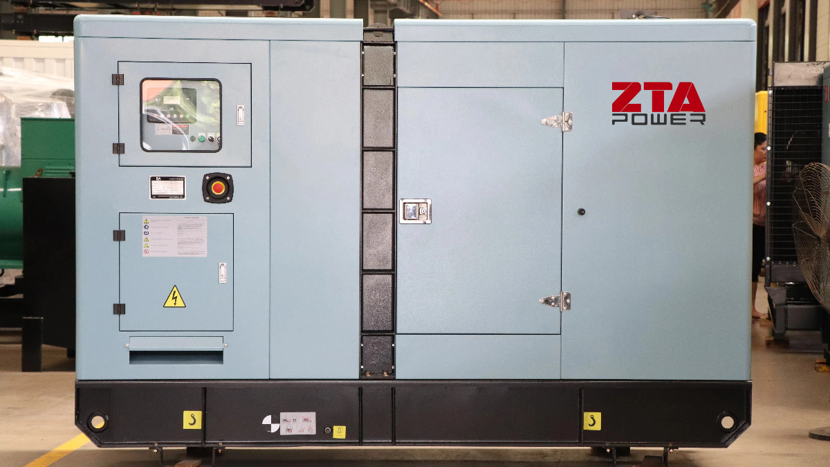
How to Calculate Generator Capacity Based on Starting Current – Cummins Engineering Guidelines
Selecting the correct emergency generator capacity is critical for cost efficiency and operational reliability. Unlike standardized methods for transformers, China currently lacks a unified calculation formula for generator sizing, leading to common errors:
Arbitrary selection (10-20% of transformer capacity)
Over-sizing (wasting capital)
Under-sizing (failing during emergencies)
Cummins Engineering Department provides these scientifically validated approaches:
1. Planning/Preliminary Design Phase
Rule of Thumb:
Generator capacity = 10-20% of total transformer capacity
Example: For a 2,000kVA transformer → 200-400kVA generator
2. Detailed Design Phase (Load-Based Calculation)
Classify building loads into three categories:
| Load Type | Examples | Inclusion Criteria |
| Critical (Mandatory) | Fire pumps, emergency lighting, elevators, smoke control systems, data centers | Always include |
| Essential (Conditional) | General lighting, non-emergency elevators, corridor lighting | Include if: • High-availability facility • Unstable grid power |
| Non-Essential | HVAC, general pumps, non-critical equipment | Exclude |
Key Insight
Fire mode: Only critical loads operate
Non-fire blackout: Critical loads are inactive
Never simply sum all loads – this causes 30-50% oversizing
3. Starting Current Considerations
Account for motor inrush currents (typically 6x rated current):
Step 1: List all motors with starting sequence
Step 2: Apply diversity factors:
Simultaneous starts: 1.0
Staggered starts: 0.5-0.7
Step 3: Use formula:
Generator kVA = (ΣRunning Loads + Σ(Starting Current × Diversity Factor)) / 0.8 (PF)
Example:
100kW fire pump (600A starting current)
50kW emergency lighting (no inrush)
Diversity factor: 0.6
Generator kVA = [(50 + 100) + (600 × 0.6)] / 0.8 = (150 + 360) / 0.8 = 637.5kVA → Select **650kVA**
Cummins-Specific Recommendations
For data centers/hospitals: Add 20% margin to calculated capacity
For industrial plants: Use load profiling software (PowerCommand® 4.0)
ZTA POWER's Generator Sizing Methodology
For optimal emergency generator capacity selection, ZTA POWER recommends choosing the larger value from the following two calculation methods, incorporating both load diversity and motor starting requirements:
1. Base Load Calculation
Formula:
P=k×PjηP=ηk×Pj
Where:
PP = Generator power (kW)
Pj=Kx×PΣPj=Kx×PΣ (Calculated load)
KxKx: Demand factor (0.85–0.95)
PΣPΣ: Total connected load (kW)
ηη: Parallel operation unbalance factor (0.9 for multiple units, 1 for single)
kk: Safety factor (1.1)
2. Motor Starting Capacity Verification
Method A: Starting kVA Requirement
P=(PΣ−Pm)ηΣ+Pm×K×C×cosψm(kW)P=ηΣ(PΣ−Pm)+Pm×K×C×cosψm(kW)
Parameters:
PmPm: Largest motor/group starting power (kW)
ηΣηΣ: System efficiency (0.85)
cosψmcosψm: Motor starting PF (0.4)
KK: Motor starting current multiple (typically 6–7x)
CC: Starting method coefficient:
Direct-on-line: 1.0
Y-Δ: 0.67
Auto-transformer:
50% tap: 0.25
65% tap: 0.42
80% tap: 0.64
Method B: Voltage Dip Limitation
P=Pn×K×Xd′′×(1ΔE−1)(kW)P=Pn×K×Xd′′×(ΔE1−1)(kW)
Parameters:
Xd′′Xd′′: Generator transient reactance (0.25)
ΔEΔE: Allowable voltage dip:
With elevators: 20%
Without elevators: 25%
Special Case: VFD-Driven Motors
For facilities using variable frequency drives (VFDs)
Starting current drops to 1.5–2x rated current
Voltage dip < 5%
Simplified approach: Ignore starting current; size based on calculated load (PjPj) only
ZTA POWER Recommendations
Industrial Plants: Prioritize Method A (starting kVA) for heavy machinery
Commercial Buildings: Emphasize Method B (voltage stability) for sensitive loads
Hybrid Approach:
Calculate both methods
Select the higher value
Add 10% margin for future expansion
Pro Tip: For mission-critical facilities (hospitals/data centers), conduct transient analysis using software like ETAP.
Always verify with transient response tests (must recover voltage within 2 seconds)
