Diesel Generator Fuel Supply System: Comprehensive Technical Guide
Diesel Generator Fuel Supply System: Comprehensive Technical Guide
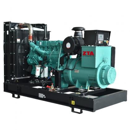
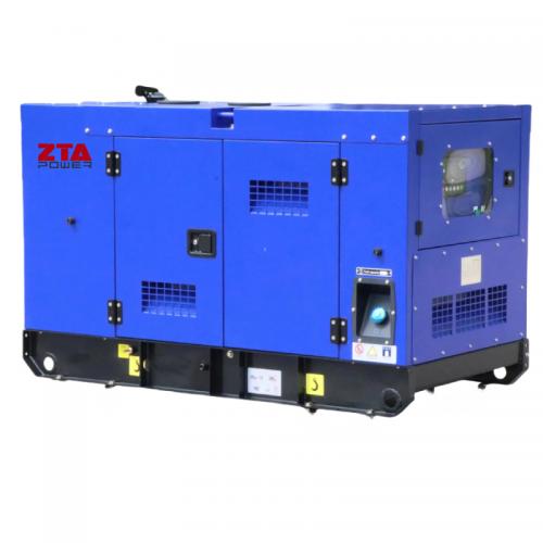
The fuel supply system is a critical component of diesel generators, directly impacting power output, fuel efficiency, noise levels, and emissions. This system consists of:
These components work together to deliver precisely metered fuel into the combustion chamber for optimal air-fuel mixing and combustion.
1. Fuel Tank
Construction:
Features:
Common Failures & Solutions:
2. Fuel Feed Pump
I. Function
Maintains fuel circulation in low-pressure circuit
Delivers filtered fuel to injection pump at required pressure (typically 0.2-0.6MPa)
Common types: Piston, vane, and rotary (rotary pumps used in distributor-type systems)
II. Piston-Type Pump Structure
(Standard in 135-series/B-series Cummins generators)
Key Components:
Main assembly:
Drive mechanism:
Pushrod with return spring
Roller tappet (maintains contact with camshaft eccentric)
Priming pump:
Manual piston pump
Rubber seals
Operating button
Priming Pump Purposes:
Pre-lubricates system before startup
Bleeds air from fuel lines to prevent unstable operation
III. Operating Principle
1.Camshaft eccentric drives piston reciprocation
2.Creates suction through inlet valve (intake stroke)
3.Pressurizes fuel through outlet valve (discharge stroke)
4.Self-regulates delivery volume based on engine load
IV. Critical Assembly Specifications
Technical Note: Modern systems often incorporate:
Electronic unit pumps (EUP)
Common rail technology
Adaptive pressure control (10-300MPa variable)


 IPv6 network supported
 English
 français
 русский
 español
 português
 العربية
 Türkçe
 ไทย
ไทย Tiếng Việt
 Indonesia
  Filipino